

Kerb Ramps- That are not in the direct Continuous Accessible Path of Travel
Course: DD-015 | Length: 6:10 mins | Instructor: Dean Homicki

Chapters
00:25 - Learning Overview
01:59 - Learning Session
02:27 - Let’s Begin
05:29 - Learning Resources
Transcript
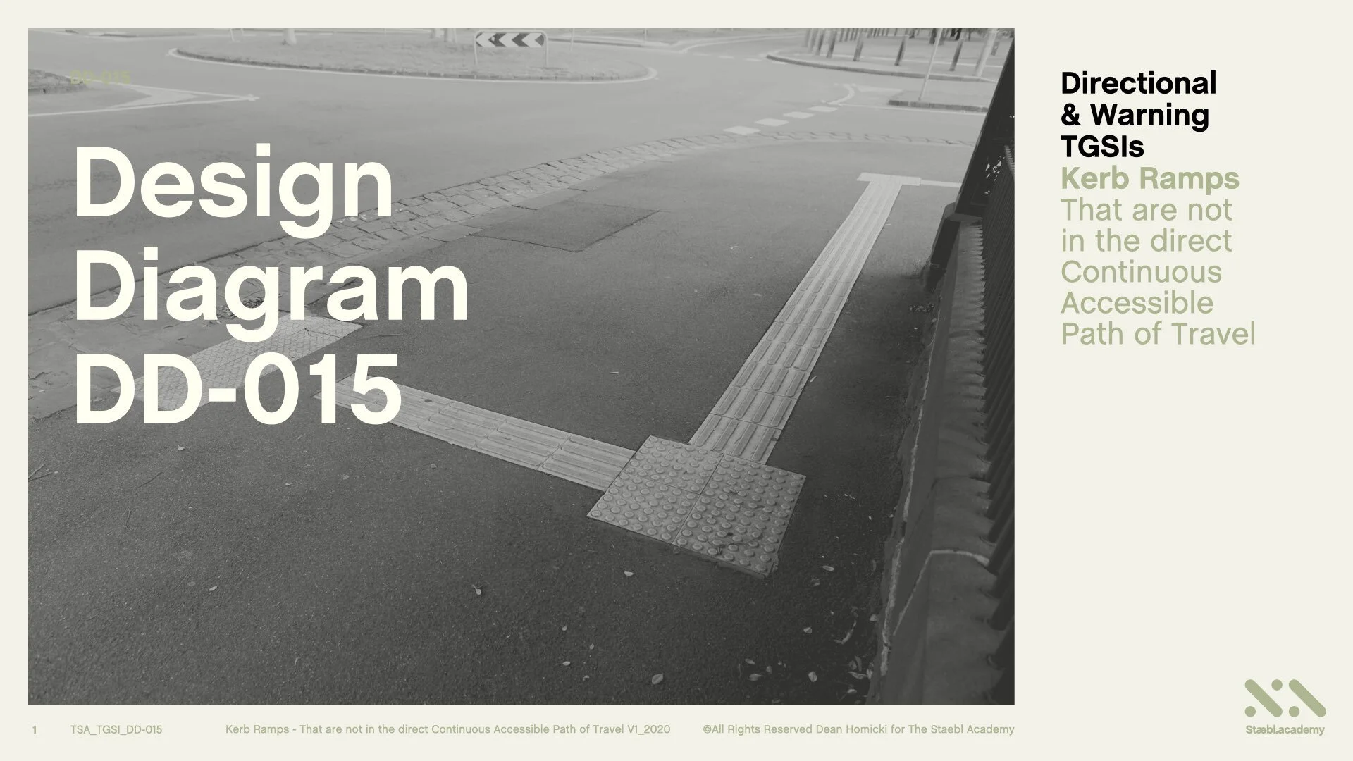
This learning session will cover the use of Directional and Warning TGSIs with:
Kerb Ramps that are not in the Direct Continuous Accessible Path of Travel.
Welcome to staebl.academy TGSI Design Diagram 015. I’m Dean Homicki and I’ll be your guide for this course.
Learning Overview
Let’s review one type of use of Directional and Warning TGSIs with Kerbs Ramps and together extract what the Australian TGSI Standard requires of the situation.
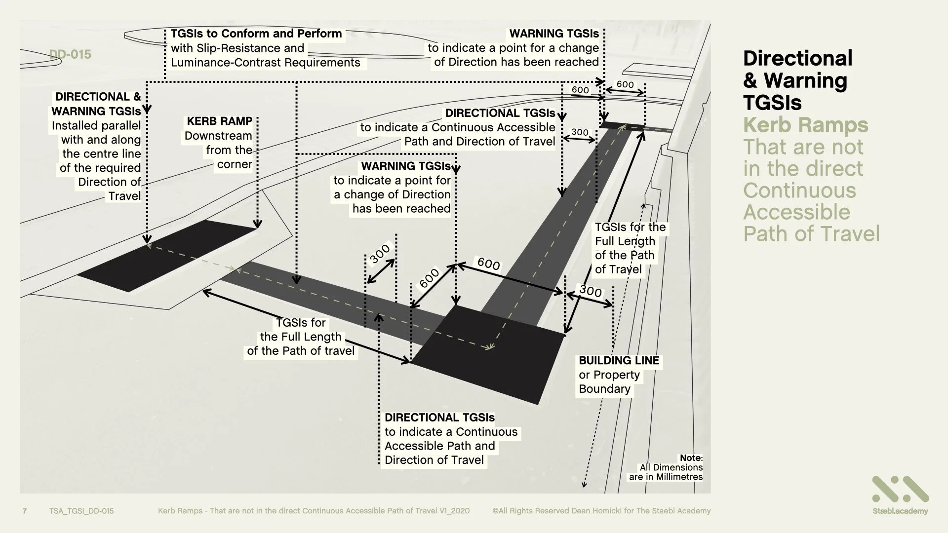
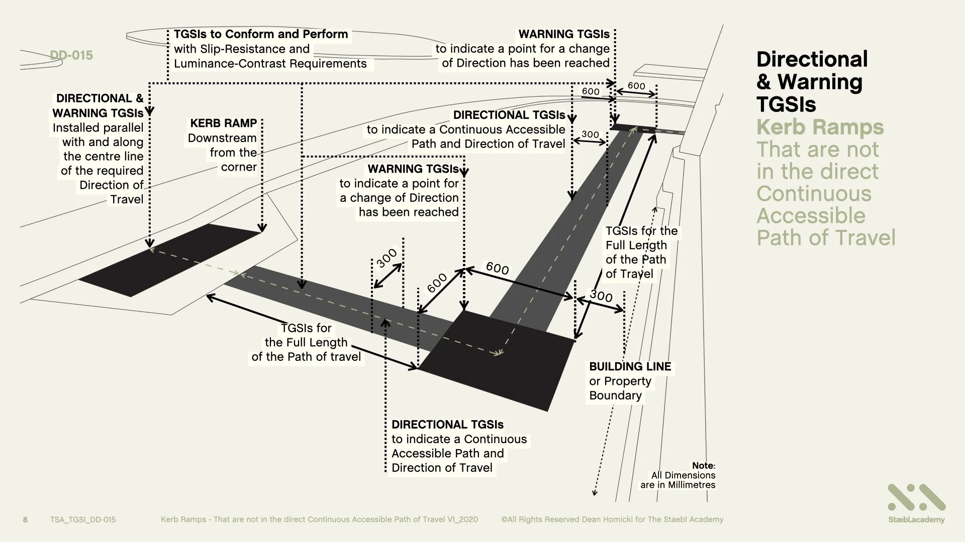
Where a Kerb Ramp is not in the Direct, Continuous Accessible Path of Travel, or, able to be orientated with other tactile cues, (like walls, handrails or building frontage), Directional TGSIs are required to indicate an Accessible Continuous Path and Direction of Travel, leading to Warning TGSIs located at the Kerb Ramp Crossing or Entry point.
The use of Directional TGSIs shall be arranged with a width of 300 mm, installed parallel with and along the centre line of the required Direction of Travel and, for the full length of Path of Travel, providing for persons who are blind or vision-impaired safe orientation and travel through to their destination.
TGSIs for this application shall also conform and perform, with the applicable Slip Resistance and Luminance Contrast Requirements.
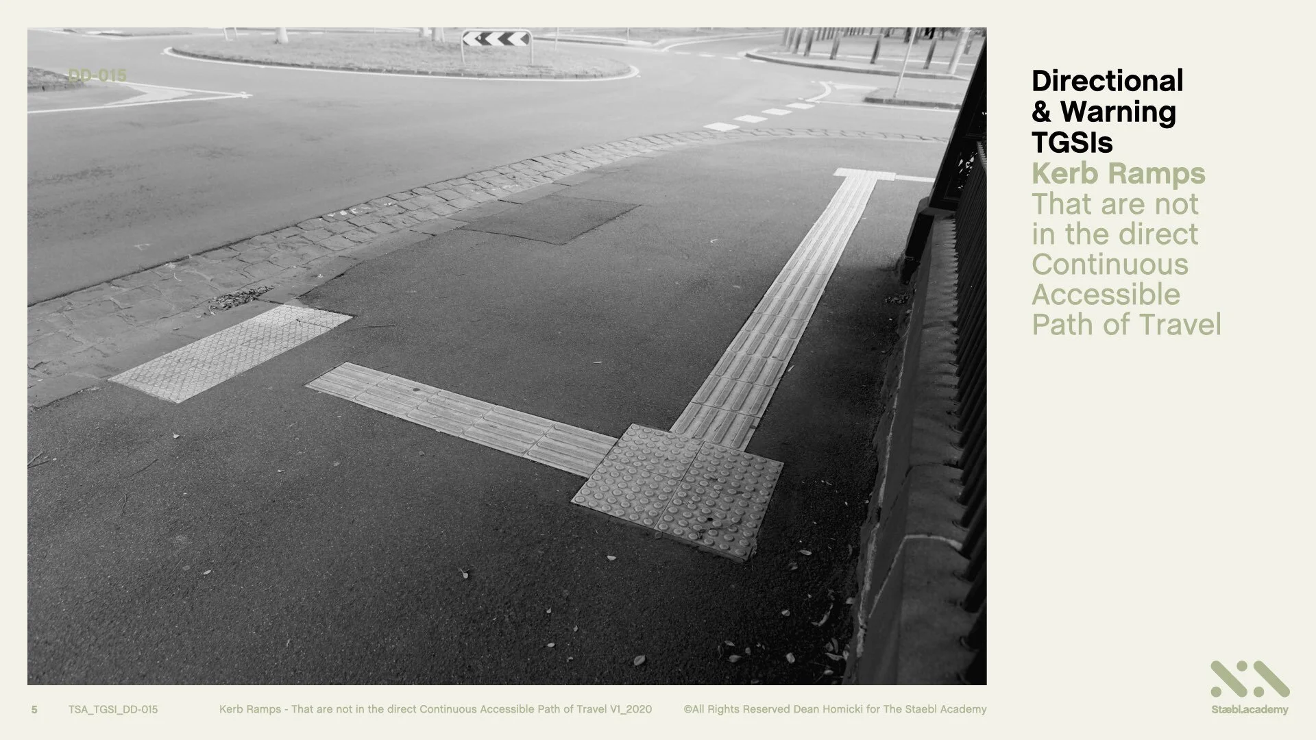
Here is a real-life example of an open space with Integrated Directional and Warning TGSIs installed. We are going to now convert this image it into a perspective line drawing and view how TGSIs have been used in this application.
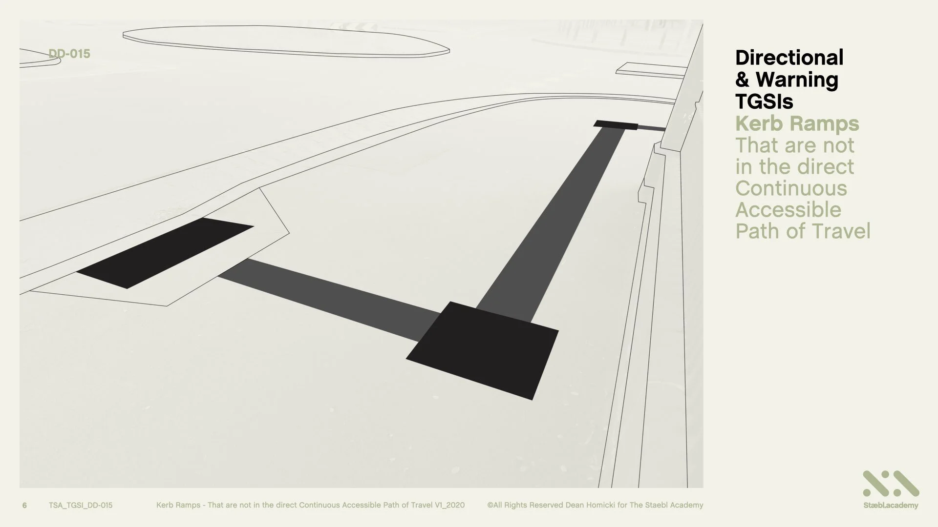
Here’s the line drawing of the image.
Learning Session
How to use TGSIs in this situation
In this example, the Kerb Ramp used in this Pedestrian Crossing is not in the direct continuous accessible path of travel.
For the orientation of persons who are blind or vision impaired, applying this knowledge enables us to determine how to use TGSIs and conform to the Normative and Informative Guidelines of the Australian TGSI standards.
Let’s Begin
In this public pedestrian space, we see an ‘Open Area’ - This Open Area has is insufficient directional orientation from tactile cues, like walls or buildings, to guide a pedestrian safely to the Kerb Ramp Crossing or Entry Point.
The absence of these tactile cues makes this Open Area a hazard for persons who are blind or vision-impaired, as they may experience difficultly in orientating their self safely through the space towards their destination and locating the Pedestrian Crossing.
We can view here the ‘Accessible Continuous Paths of Travel’. These Paths are from East to West and, North to South. These ‘Accessible Continuous Paths of Travel’ are not in direct alignment with any kind of Kerb Ramp Pedestrian Crossing.
Each Continuous Path of Travel terminates at the Carriage way which is a potentially very hazardous for pedestrians. These ‘Accessible Continuous Paths of Travel’ are not in direct alignment with any kind of Kerb Ramp Pedestrian Crossing.
Each Continuous Path of Travel terminates at the Carriage way which is a potentially very hazardous for pedestrians.
So how have TGSIs been used in this situation?
Where the Accessible Path of Travel reaches a point for a Change of Direction, Warning TGSIs are applied to a width of 600 mm and, to a depth of 600 mm. This equates to 12 x 12 TGSI nodes at 50 mm spacings.
Directional TGSIs have been used to indicate a safe and accessible path and direction of Travel. In this situation, Directional TGSIs are 300 mm wide. This equates to 4 TGSI Truncated Bars at 75 mm spacings and, are applied for the full length of the Path of travel.
Again, where the Accessible Path of Travel reaches a point for a Change of Direction, set back 300 mm +/- 10 mm from the Building Line or Property Boundary, Warning TGSIs are applied to a width of 600 mm and, to a depth of 600 mm. This equates to 12 x 12 TGSI nodes at 50 mm spacings.
After a Change of Direction has been decided, Directional TGSIs continue to indicate a safe and accessible Path of Travel to the destination.
In this situation, Directional TGSIs are 300 mm wide. This equates to 4 TGSI Truncated Bars at 75 mm spacings and, are applied for the full length of the Path of Travel. The Directional and the Warning TGSIs must be Installed parallel with and along the centre line of the required Direction of Travel.
TGSIs for this application, also need to conform and perform, with the applicable Slip-Resistance and Luminance-Contrast Requirements.
And here is a real-life TGSI application once more.
Learning Resources
That’s the conclusion for Directional and Warning TGSIs on Kerb Ramps that are not in the direct Continuous Accessible Path of Travel.
You can also access this course as a concise series of design diagrams in the resource section of our website staebl.academy/design. To access this resource now, click on the link below this video.
Thanks for joining me here at the staebl.academy. I look forward to guiding you through another learning session in the near future. Bye for now.
Listen
Click/Tap the audio player below to listen to the written transcript of this design session as an audible version. This is a streamed broadcast from the Staebl.academy site.
Diagrams
Click/Tap on an image from this learning session to view it as a larger picture. You will then be able to scroll through each individual design diagram in this slide-deck for a closer inspection.


Sources
TSA-TGSI-LEARN-DD-015 - This staebl.academy course module has drawn information from the following sources:
AS/NZS 1428.4.1: 2009 Design for Access and Mobility: Means to assist the orientation of people with a vision impairment - Tactile Ground Surface Indicators - Section 2, 2.2, 2.3.1 General, 2.3.2, Fig 2.1 (a), (b) & (c) AMDT No.2 Dec 2014. Section 3, 3.1 General (b) & (c), 3.2.1 General, 3.2.2, 3.2.3 (a), (b), (c), (d), (e) & Notes (1) and (2), Fig 3.1 (a), (b), (c) & (d) 3.3 & Fig. 3.2, Appendix A, A3.1, A3.3 (c) & (d), Appendix C (B) Paragraph 1, C3, 3 Notes (b) & (c), Fig C1.
AS 1428.1: 2009 General Requirements for Access - New Building Work - 10.7 Kerb Ramps 7.1 & Fig. 23 (a)
