

TGSI Design Requirements
Discrete Directional TGSIs
Course: DD-023 | Length: 6:43 mins | Instructor: Dean Homicki
Chapters
00:24 - Learning Overview
01:22 - Learning Session
01:40 - Let’s Begin
06:05 - Learning Resources
Transcript
This learning session will cover the use of:
Directional TGSIs and the Design Requirements for Discrete TGSI Types.
Welcome to staebl.academy TGSI Design Diagram 023. I’m Dean Homicki and I’ll be your guide for this course.
Learning Overview
We begin by asking,
‘How are Discrete TGSIs defined in the Australian TGSI Standard?’
The Australian TGSI Standard describes a Discrete TGSI as, ‘Tactile Ground Surface Indicators (TGSIs) that are individually installed, which provide the same Luminance for the Sloping Sides, and Upper the Surface of the Truncated Cone.’
What are the Design requirements of Discrete TGSIs?
There are two types of Discrete TGSIs. These types are defined as Discrete Warning TGSIs and Discrete Directional TGSIs. In this learning session, we will review Discrete Directional TGSIs.
Learning Session
Let’s take a closer look at the technical details outlined in Figure 3.1, Amendment No.1, of the Australian TGSI Standard. A summarised version of these requirements follows herein.
Let’s Begin.
The Truncated Bars of Discrete Directional TGSIs, shall each have:
a height of: 4 to 5 mm above the entire Base Surface,
shall be of a length of between: 240 to 590 +/- 2 mm,
with Drainage Gaps of: 10 +/- 2 mm at 250 to 600 mm centres,
have a diameter at each base of: 35 +/- 1 mm,
have a diameter at each Upper Surface of: 25 +/- 1 mm and
each be evenly spaced apart in a defined pattern (Arrangement) of 75 +/- 5 mm, measured from the centre of each Truncated Bar.
Each Discrete Directional TGSI must have, Luminance-Contrast to the background, or, the adjacent Path of Travel as follows:
Discrete: Not less than 45% Luminance Contrast across its entire area.
Each Discrete Directional TGSI unit shall be slip-resistant.
In Australia, to determine a TGSI’s slip-resistance rating and it’s classification, the trafficable surface of the TGSI needs be tested in accordance with AS 4586: 2013 and, installed in conjunction with Standards Australia Handbook HB 198: 2014 - Guide to the specification and testing of slip resistance of pedestrian surfaces.
Let’s take a look at the dimensionality of Discrete Directional TGSIs.
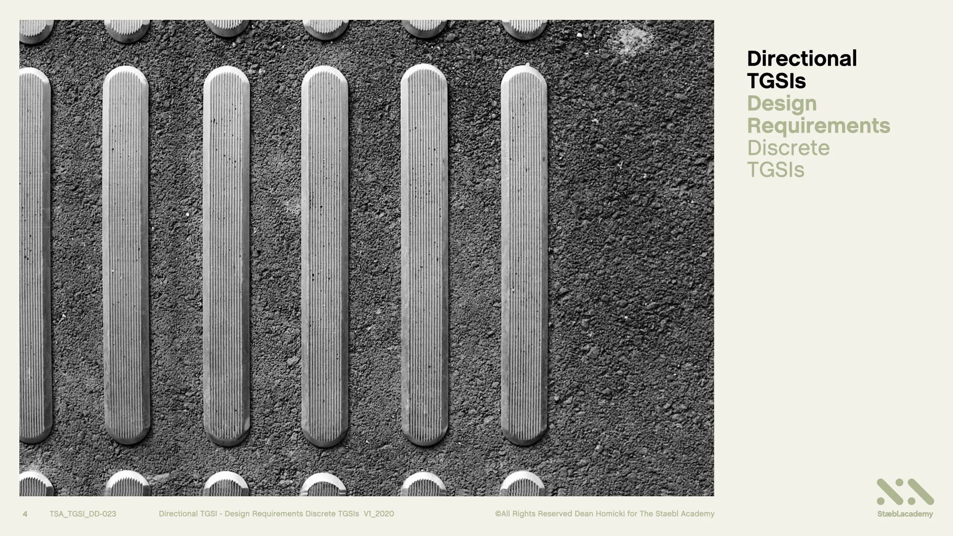
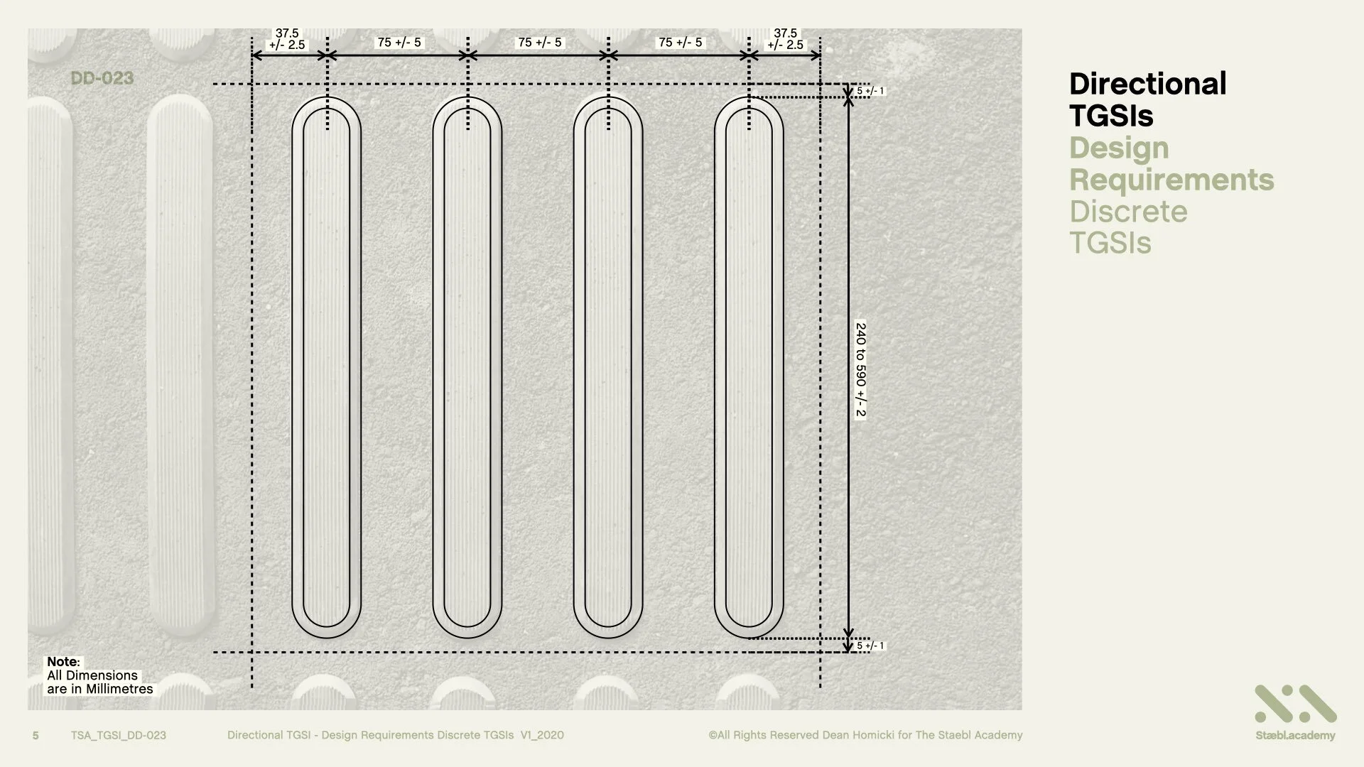
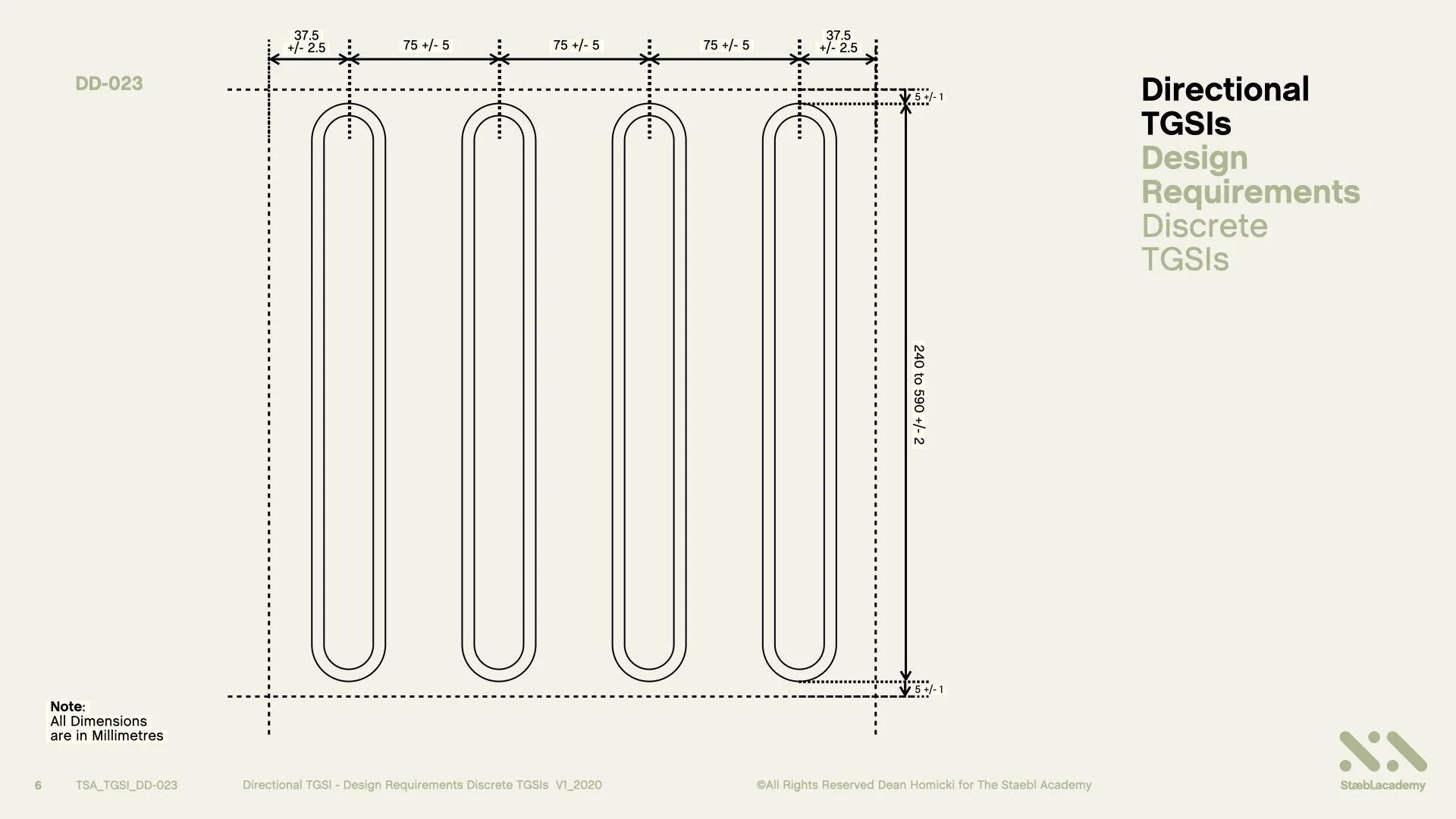
We begin with a real-life installation of 316 Stainless Steel Discrete Directional TGSIs. We are going to now convert this image into a Plan view line drawing and reveal the dimensionality of the TGSI Arrangement (Pattern).
Here’s the line drawing of the image.
The Truncated Bars are evenly spaced apart in a defined pattern (Arrangement) of 75 +/- 5 mm. This spacing is measured from the centreline of each Truncated Bar along its length to the centre of adjacent Truncated Bar. The Truncated Bars must also be parallel to each other. When Discrete Directional TGSIs are installed together, (side-by-side), it is important that the 75 +/- 5 mm spacing, between each Truncated Bar, is maintained.
To determine the arrangement (Pattern) for the Width of a Discrete Directional TGSI installation, a distance of 37.5 +/- 2.5 mm, is measured from the centre of the Upper Surface of the Truncated Bar, to locate the perimeter edge. This dimension should be observed to ensure conformance to the many installation criteria of TGSIs.
The length of the Truncated Bar at its Base Surface shall be between 240 to 590 +/- 2 mm. When Discrete Directional TGSIs are installed together, (end-to-end), along a Continuous or Path or Direction of Travel, it is important that the Drainage Gaps of 10 +/- 2 mm between each Truncated Bar is maintained.
To determine the arrangement (Pattern) for the Length of a Discrete Directional TGSI installation, a distance of 5 +/- 1 mm, is measured from the base of the each Truncated Bar to locate the perimeter edge. This dimension should be observed to ensure conformance to the many installation criteria of TGSIs.
These measurements will also achieve the correct arrangement of Discrete Directional TGSIs with Figure 3.1 of the Australian TGSI standard.
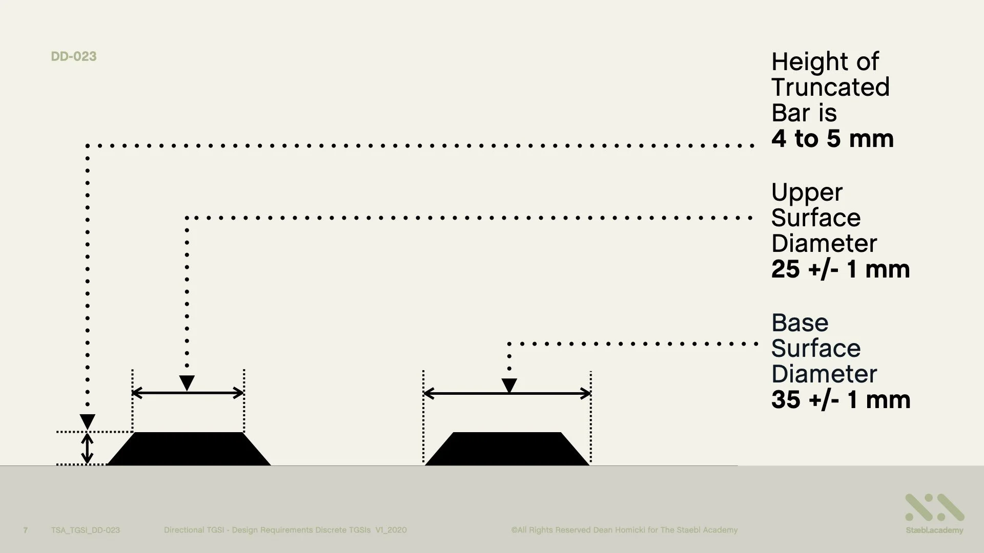
In an Elevation View of the Discrete Directional TGSIs, we can see that, the Height of each Truncated Bar is 4 to 5 mm, that the Upper Surface Diameter of is 25 +/- 1 mm, and that the Base Surface Diameter 35 +/- 1 mm.
Learning Resources
That’s the conclusion for Design Requirements of Discrete Directional TGSIs
You can also access this course as a concise series of design diagrams in the resource section of our website staebl.academy/design. To access this resource now, click on the link below this video.
Thanks for joining me here at the staebl.academy. I look forward to guiding you through another learning session in the near future. Bye for now.
Listen
Click/Tap the audio player below to listen to the written transcript of this design session as an audible version. This is a streamed broadcast from the Staebl.academy site.
Diagrams
Click/Tap on an image from this learning session to view it as a larger picture. You will then be able to scroll through each individual design diagram in this slide-deck for a closer inspection.


Sources
TSA-TGSI-LEARN-DD-023 - This staebl.academy course modules has drawn information from the following sources:
AS/NZS 1428.4.1: 2009 (Amendments 1 & 2) Design for Access and Mobility: Means to assist the orientation of people with a vision impairment - Tactile Ground Surface Indicators - Clause 1.4.8 (AMDT No. 1 NOV 2010), Section 2, 2.2 (b) & (b i & ii), Section 3, 3.2 General Requirements, 3.2.1 (c) & (d), 3.2.2 Design Requirements, 3.2.3, Fig 3.1 (a), (b) & (d) AMDT No.1 NOV 2010, Appendix E.E2 Luminance Contrast Requirements - 1st and 3rd Paragraph, Appendix A1 Wayfinding (b).
